Air Drop Overview
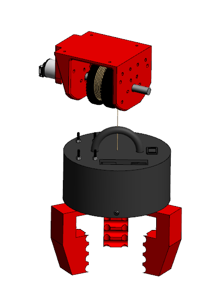
For our UAV Air Drop System, we are evaluating two designs: a rotary winch mechanism and a brake-based release system. The rotary winch provides precise, controlled deployment using a motorized spool, allowing for gradual descent and accurate placement. Alternatively, the brake-based system focuses on secure payload retention and controlled release but lacks the flexibility of dynamic descent control. The winch mechanism features a 3-jaw claw system with 3D-printed guide rails and jaws for secure and precise payload handling. It integrates an ESP32-controlled system with a LiPo battery, current sensor, motor driver, and a 3D-printed motor horn, ensuring reliable grip and smooth operation. Our final choice will prioritize reliability, safety, and compliance with competition requirements, ensuring an effective and repeatable payload delivery solution.
Claw Design
The winch mechanism features a 3-jaw claw system with 3D-printed guide rails and jaws, ensuring precise and smooth operation for securely gripping and handling payloads. The electronics are all soldered onto a prototype PCB board, with the system powered by a Gens Ace 800mAh 2S 7.4V 40C LiPo battery and controlled by an ESP32. It includes a DFRobot INA219 current sensor for monitoring and a DRV8871 motor driver for motor regulation. A 3D-printed motor horn attached to an acrylic thread provides a lightweight and customizable structure. The switch is mounted on a 3D-printed cover, and a handle is provided for the rope from the winch, allowing for easy control. The design ensures a strong, reliable grip and smooth movement for repeated use under varying loads.

This video demonstrates our brake design in action, where the winch lowers a plastic water bottle as the payload. After testing various spool radii to optimize drop time and safety, we settled on a 100 mm diameter spool, which allows the drop time to remain under 2 minutes. Larger spool diameters unwind more wire per rotation, but also add size and weight. Despite these trade-offs, the servo motor’s steady speed confirmed that this spool size provides the best balance of efficiency and performance for the winch system. The video shows a successful drop, highlighting the precision and reliability of the design for controlled payload deployment.
This video demonstrates our updated claw design in action, where the winch lowers the rope tied to the 3-jaw claw mechanism. The strobing beacon payload is carefully placed on the ground in just 4 seconds. With a minimum air drop altitude of 75 ft, which is 6.25 times the measured height in the video, we estimate the total drop time to be under 30 seconds at this altitude. After testing various spool radii, we determined that a 60 mm diameter spool reduced the drop time to under 4 seconds from 12 ft. Once the payload is placed, the winch retracts the claw, ensuring precise and reliable operation. The motor performed steadily at this spool size, confirming the suitability of the design for efficient payload deployment and retrieval.
Brake Design
Pros:
- Simplified Mechanism – Fewer moving parts and a direct braking action reduce failure points and simplify maintenance compared to more complex motorized systems.
- Reliable Operation with Feedback – The rotary encoder, using a beam break sensor, tracks 20-degree increments in spool rotation, providing speed, position, and acceleration data for better descent monitoring.
- Improved Surface Treatment – The contact area between the brake clamp and rotor was enhanced with rubber, increasing the coefficient of friction, reducing the need for a stronger servo, and improving braking efficiency.
Cons:
- Higher Power Consumption – The MG996R servo requires continuous power to hold and release the payload, resulting in higher power consumption compared to the rotary winch system, which only uses power during descent.
- Limited Descent Control – While the brake effectively slows the payload, it lacks dynamic control over descent speed, resulting in less precise payload placement.
- Reduced Accuracy – Despite the rotary encoder feedback, sudden braking can cause oscillations or drift during payload release, reducing the overall accuracy of the drop and potentially affecting target placement.
Rotary Winch Design
Pros:
- Precision Control – Allows for gradual and controlled payload deployment, reducing impact force. The winch mechanism uses a 12V DC Motor with a 43.7:1 metal gearbox and integrated quadrature encoder, ensuring smooth and precise operation.
- Dynamic Adjustability – Uses PID tuning to regulate descent speed, preventing oscillations and ensuring smooth and accurate payload placement. The motor encoder provides high-resolution feedback, allowing for real-time adjustments.
- Improved Accuracy – Reduces oscillations for better drop placement within the target zone.
Cons:
- Increased Complexity – Requires additional components like a motor, spool, and rope.
- Potential Mechanical Failures – Risk of tether tangling or spool malfunctions.
- Slower Deployment – Takes longer to lower the payload, which could be a disadvantage in time-sensitive missions.
Conclusion
We chose the rotary winch design for its precise control, stability, and energy efficiency. With PID tuning, it ensures smooth, accurate drops while minimizing oscillations. Both the winch and brake systems use an ESP32 for control, but the brake design lacks descent control, leading to reduced accuracy and higher impact forces. The winch’s controlled deployment makes it the best choice for safe and reliable payload delivery.

