Also known as the electrical team, this subsystem designs the backbone of the drone's electrical and control infrastructure, integration of all onboard and ground station hardware, and power systems onboard the drone.

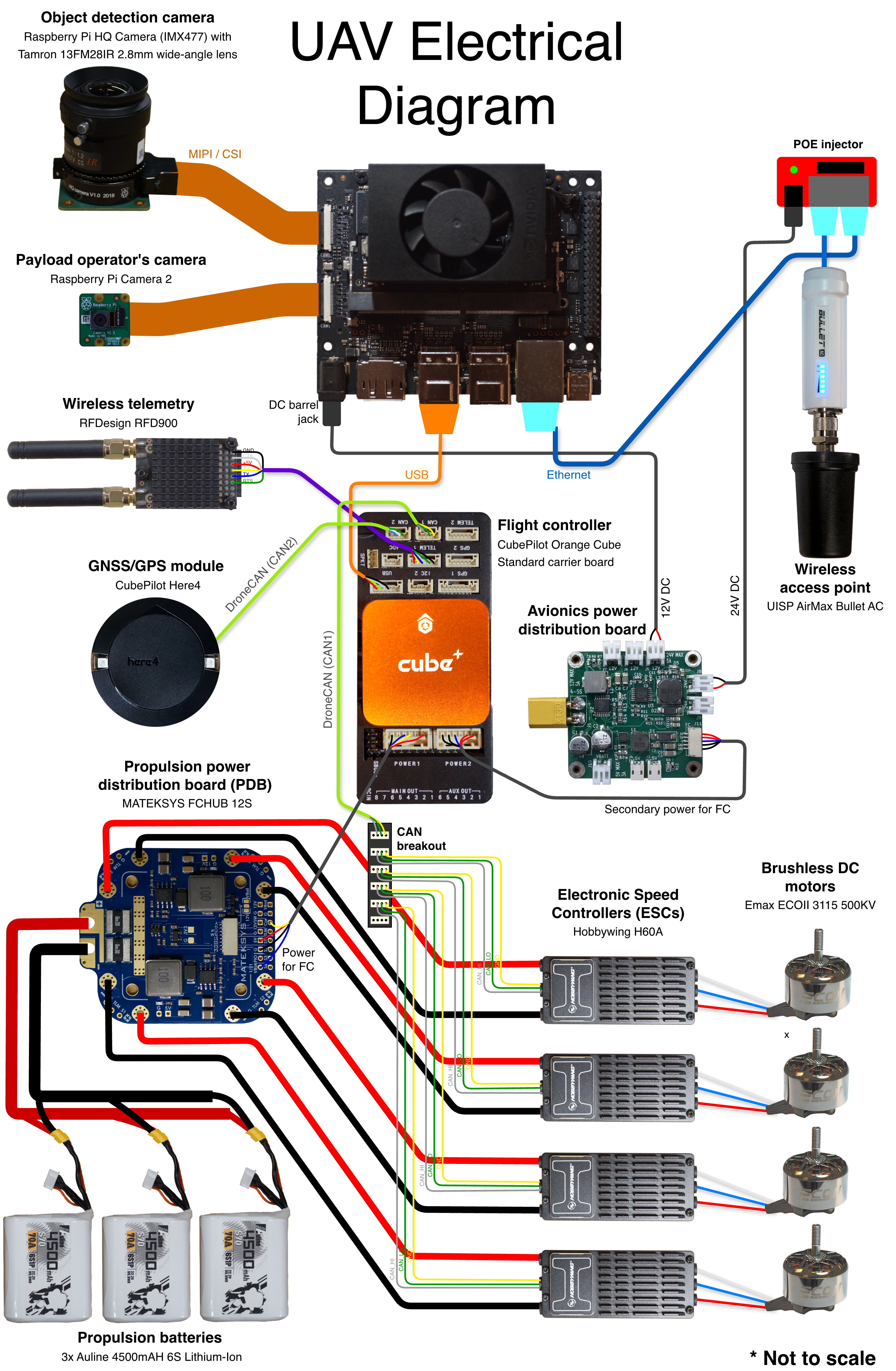
Full size diagram
Control Systems
The UAS employs a distributed control architecture consisting of a flight controller and a companion computer. The flight controller is responsible for low-level flight dynamics, stabilization, and waypoint-based navigation, while the companion computer performs computationally intensive tasks such as object detection, target-seeking navigation, aerial imaging, and mission-specific autonomous flight algorithms. Although both systems operate collaboratively, each is paired with an independent wireless communication link with its respective ground operator's control station.
The CubePilot Orange Cube serves as the primary flight controller responsible for motion control, managing stabilization, and autonomous waypoint navigation of the drone. The Orange Cube was selected for its high-performance STM32H7 microcontroller, which provides sufficient computational capability for advanced ArduPilot flight control functions. Its modular connector-based design allows access to all I/O interfaces without soldering, simplifying prototyping, assembly, and future system modifications. Flight telemetry, status data, and configuration parameters are transmitted to the ground control station through RFD900 telemetry radios, enabling mission monitoring and vehicle control using ArduPilot Mission Planner or QGroundControl software.
Positioning and navigation are provided by the Here4 GNSS receiver, which supports multiple satellite constellations to improve positioning accuracy, and startup convergence time. When used in conjunction with a Here4 Base station at the ground control station, the system supports Real-Time Kinematic (RTK) positioning, potentially achieving centimeter-level positioning accuracy.
Higher-level autonomous functions are executed on an NVIDIA Jetson Orin Nano companion computer. Using imagery captured by a Raspberry Pi HQ Camera equipped with a wide-angle lens, the Jetson processes aerial imagery to detect mission targets and ground control points, estimate their locations, and generate navigation commands that are transmitted to the flight controller. This architecture enables autonomous target acquisition and target-seeking flight while maintaining the flight controller's responsibility for vehicle stability and trajectory execution.
Communication between the companion computer and the payload operator's ground station is provided through a pair of UISP AirMax Bullet wireless access points. This wireless network system supports long-range LAN connectivity, enabling reliable command and control of mission payloads as well as real-time transmission of camera video stream and other mission data.